Case Study
Fair-Anselm Plaza
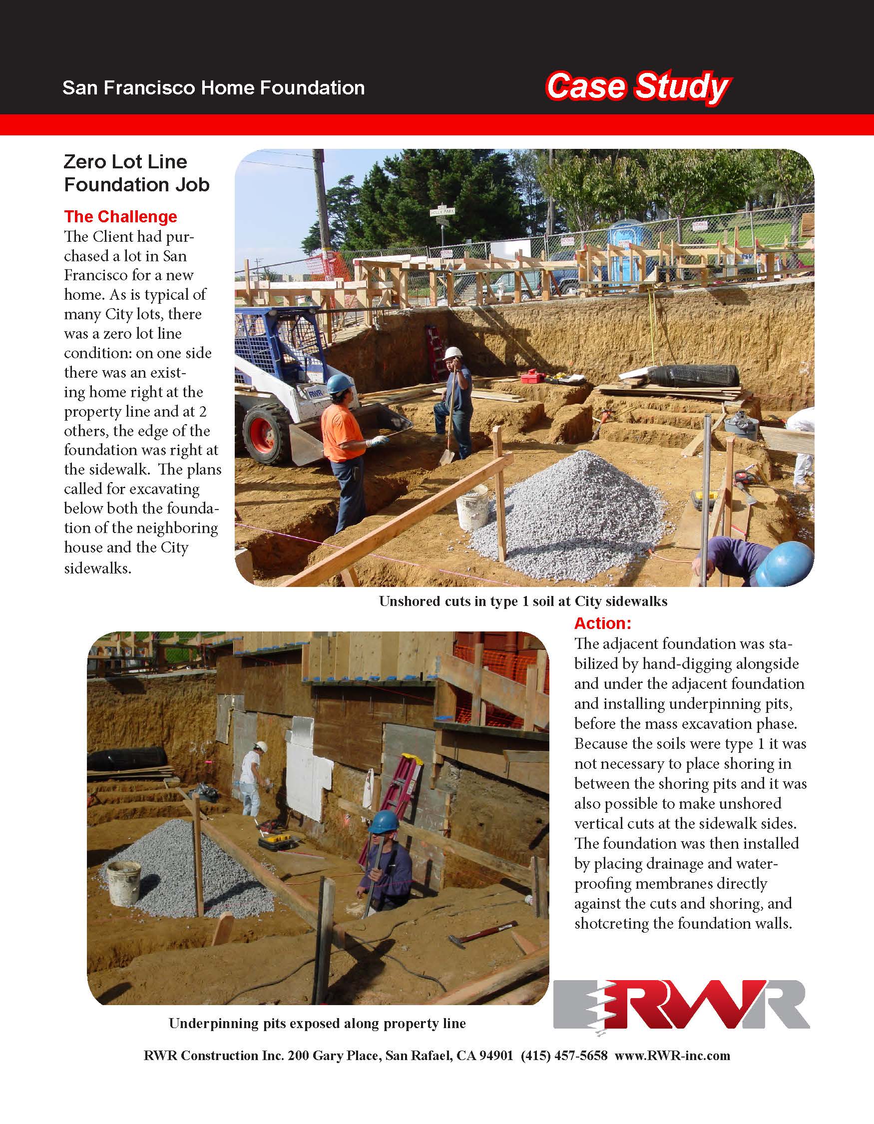
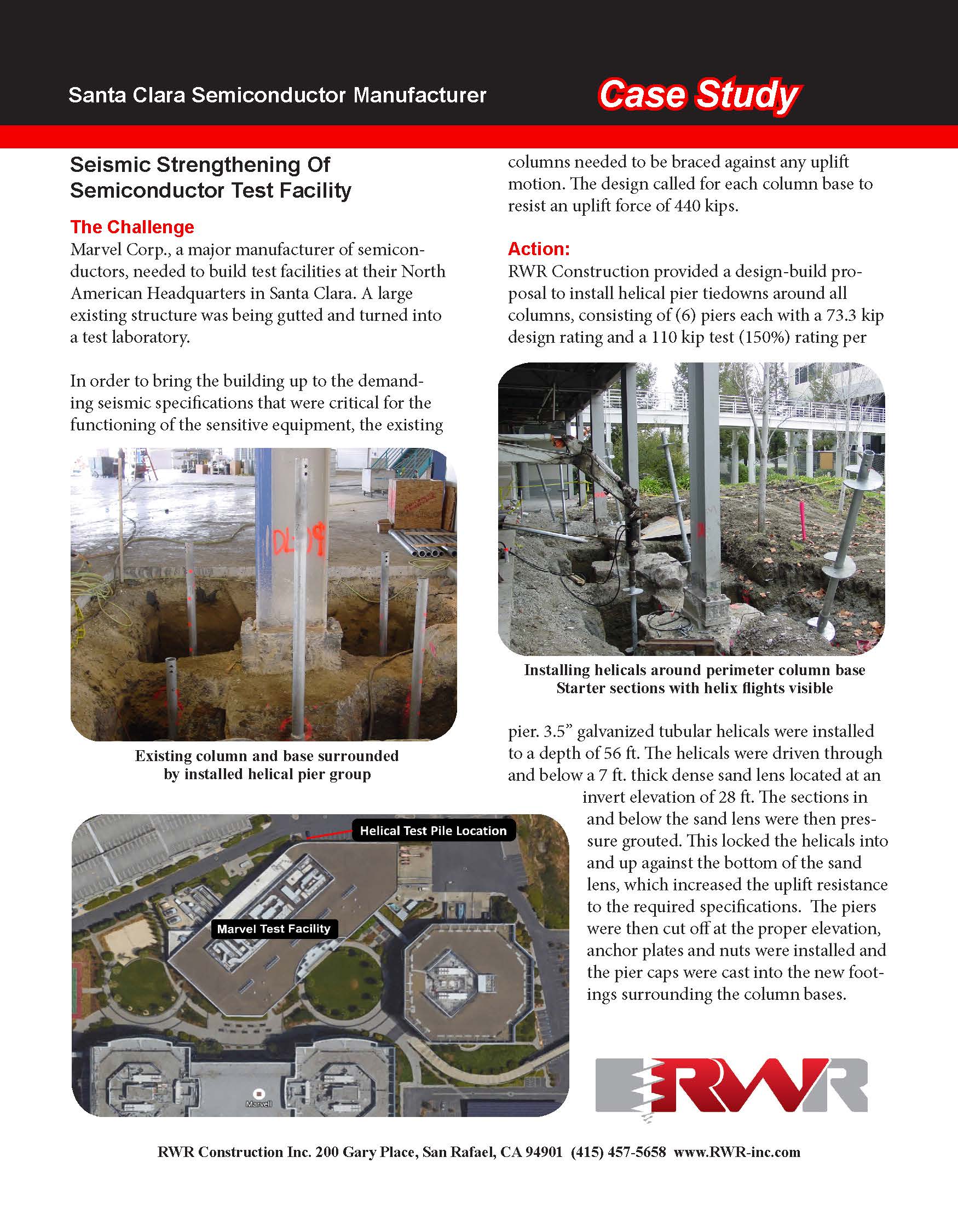
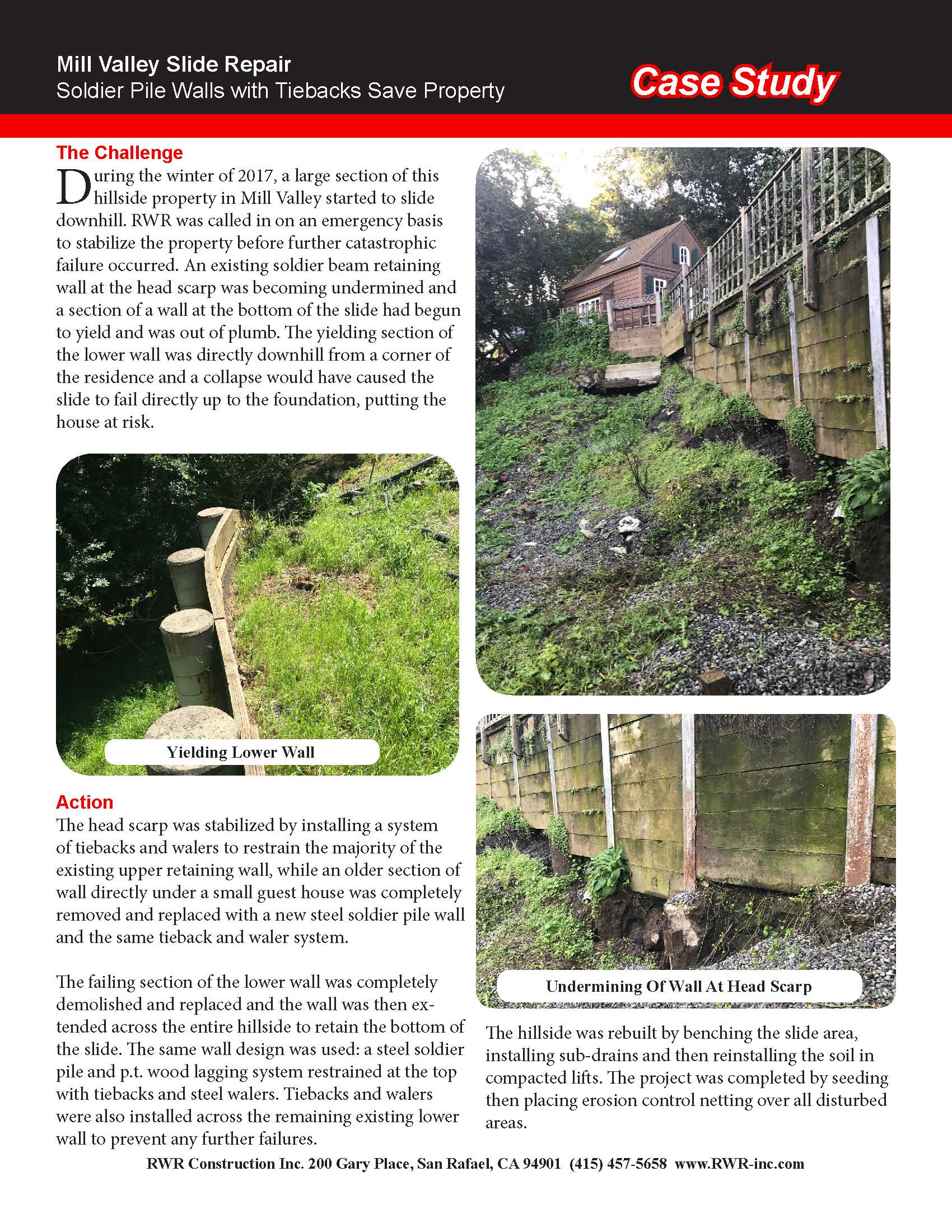
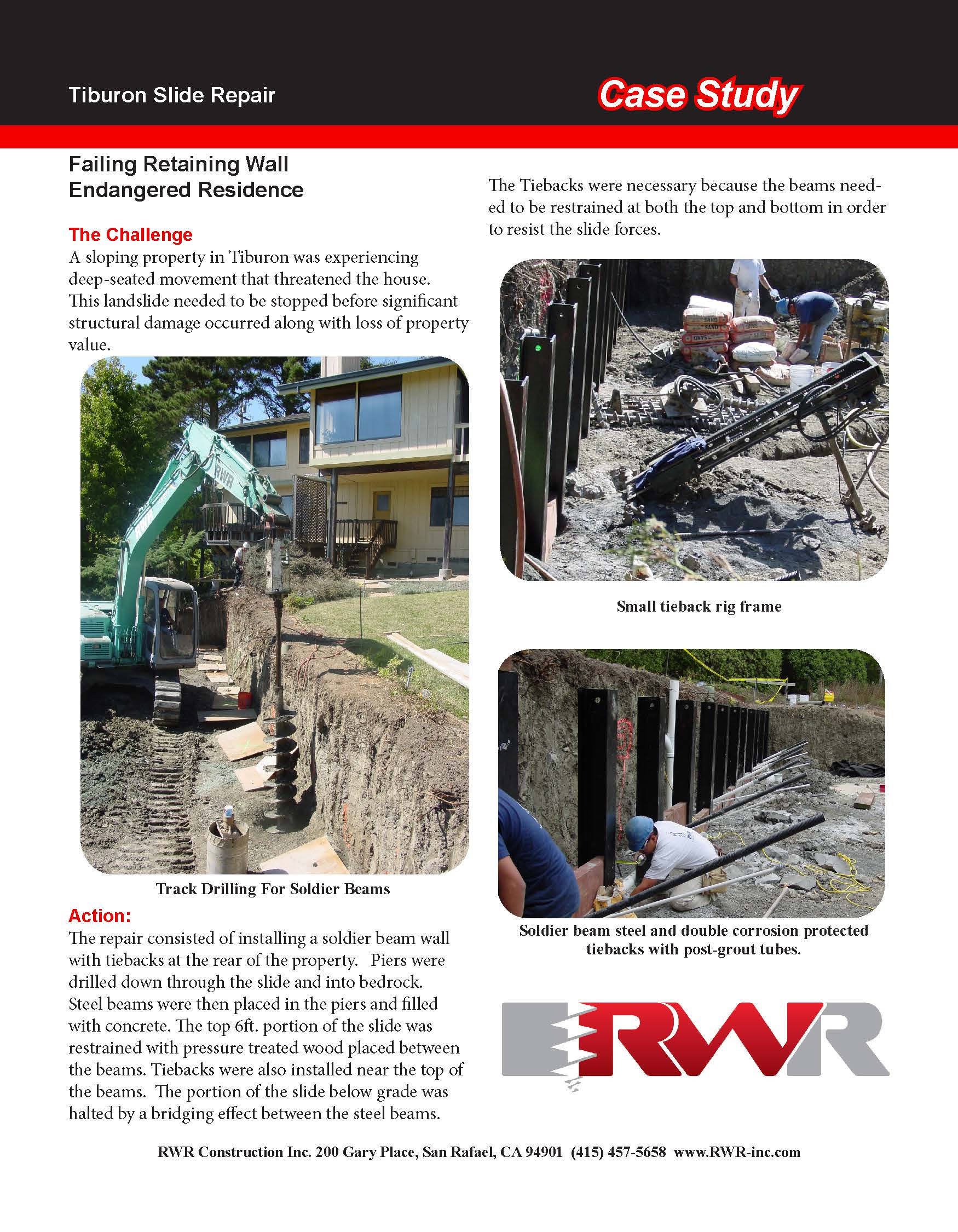
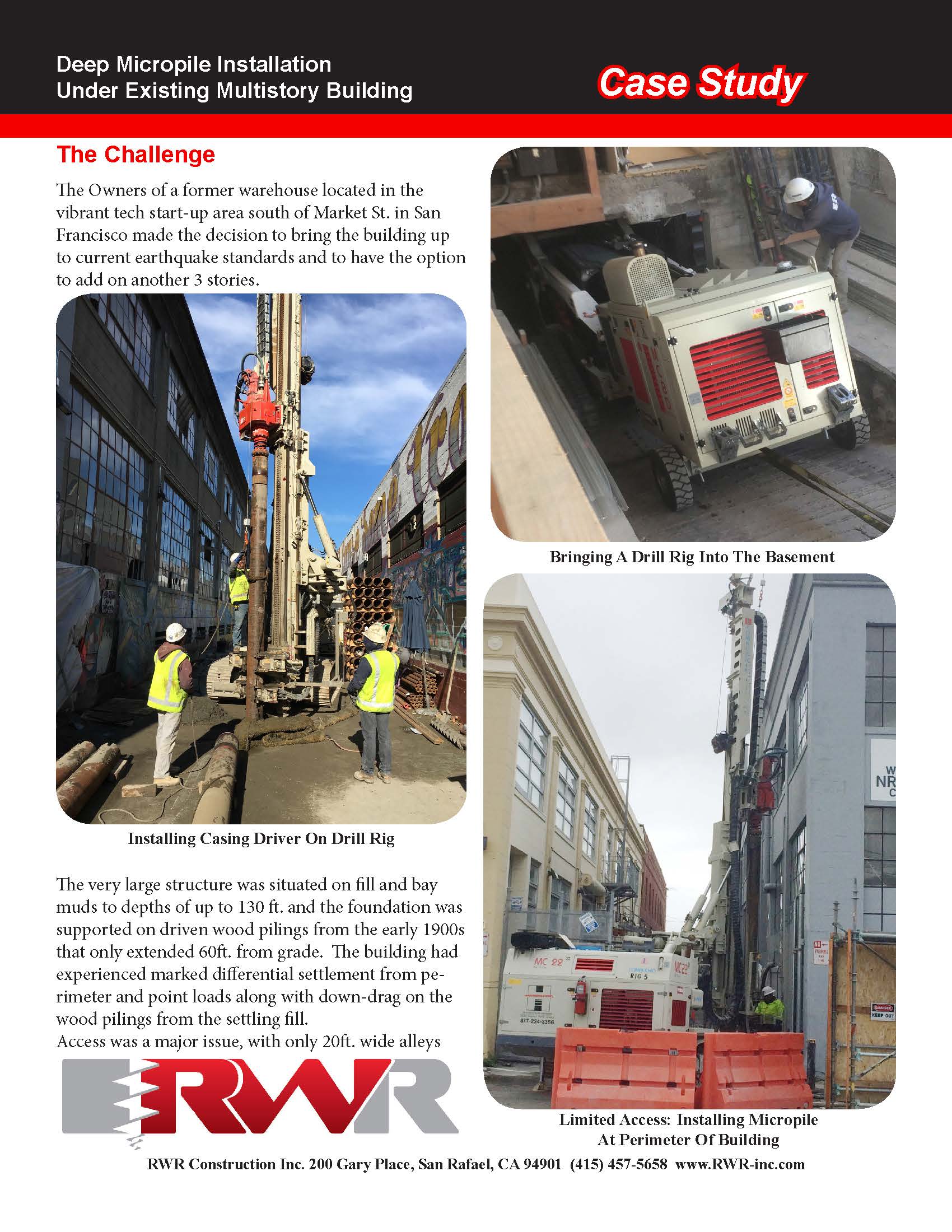
The Challenge
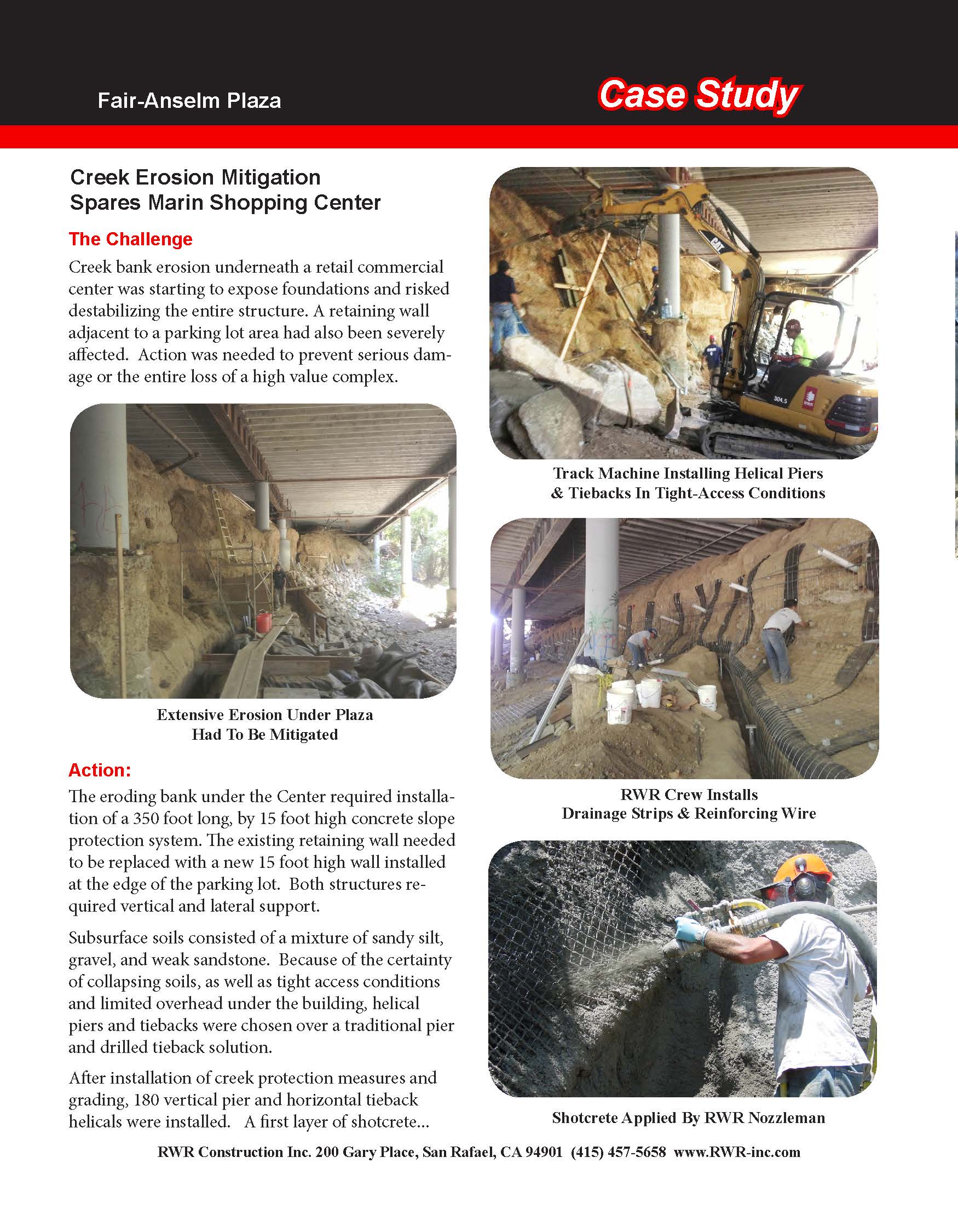
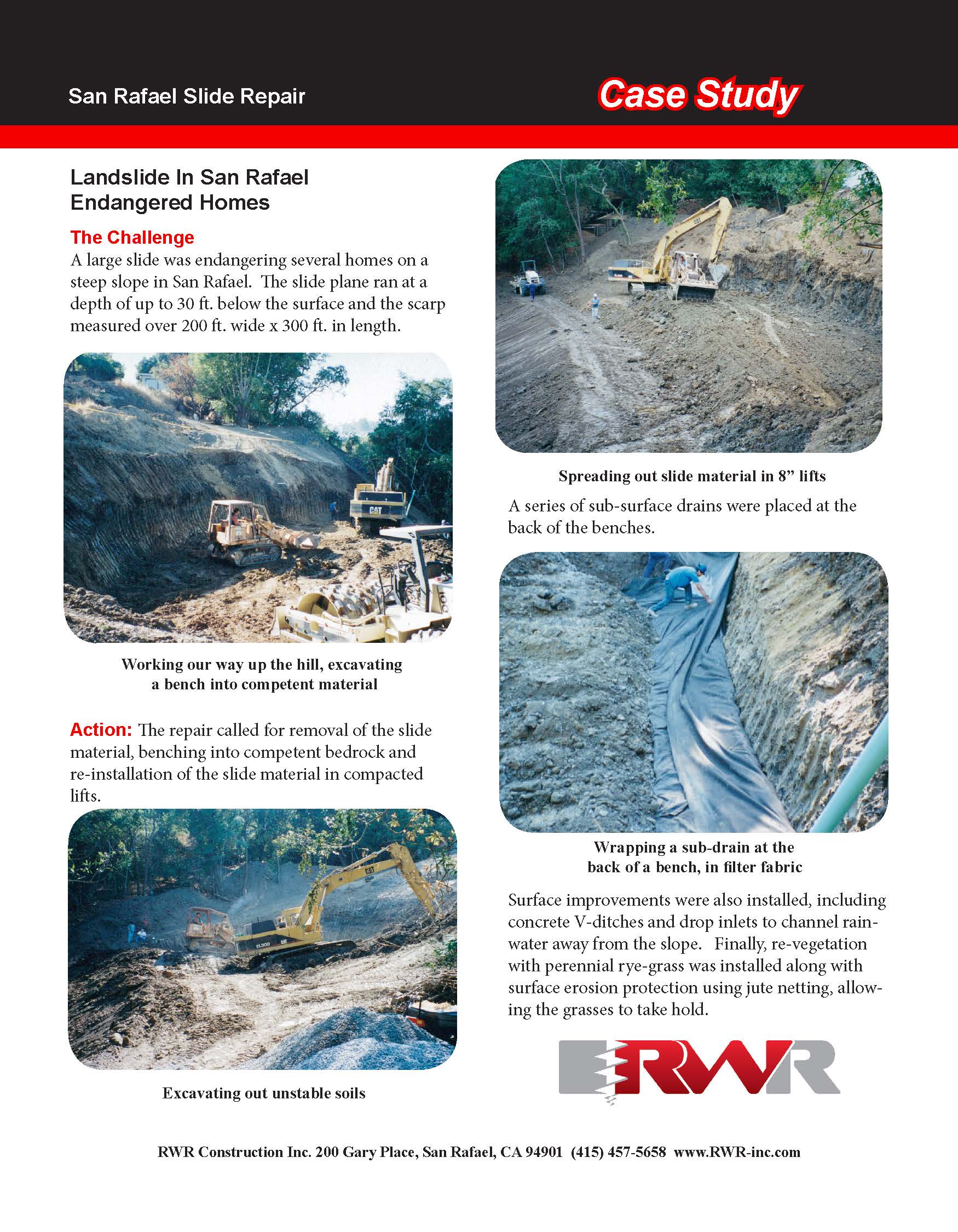
Creek bank erosion underneath a retail commercial center was starting to expose foundations and risked destabilizing the entire structure. A retaining wall adjacent to a parking lot area had also been severely affected. Action was needed to prevent serious damage or the entire loss of a high value complex.
Action:
The eroding bank under the Center required installation of a 350 foot long, by 15 foot high concrete slope protection system. The existing retaining wall needed to be replaced with a new 15 foot high wall installed at the edge of the parking lot. Both structures required vertical and lateral support.
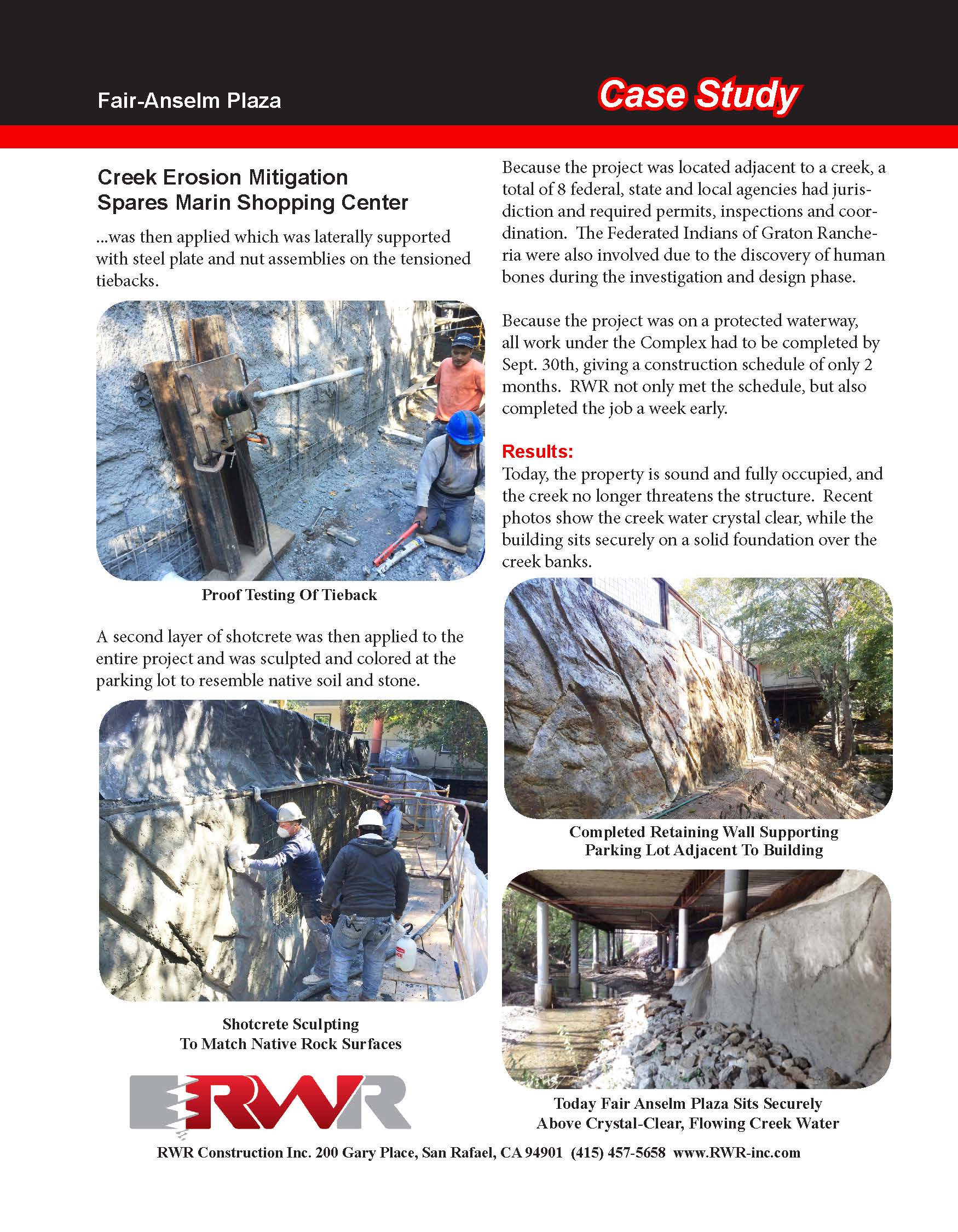
Subsurface soils consisted of a mixture of sandy silt, gravel, and weak sandstone. Because of the certainty of collapsing soils, as well as tight access conditions and limited overhead under the building, helical piers and tiebacks were chosen over a traditional pier and drilled tieback solution.
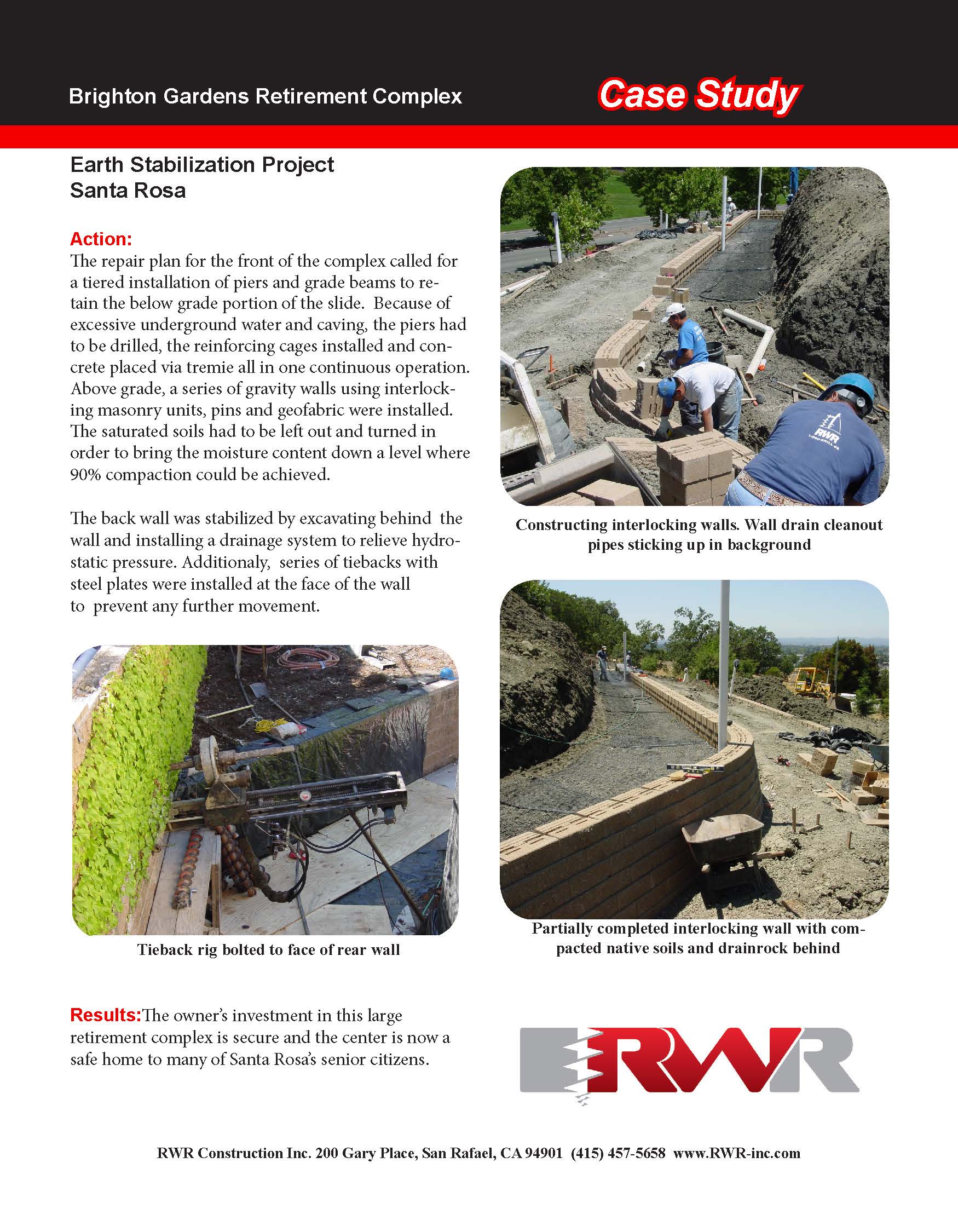
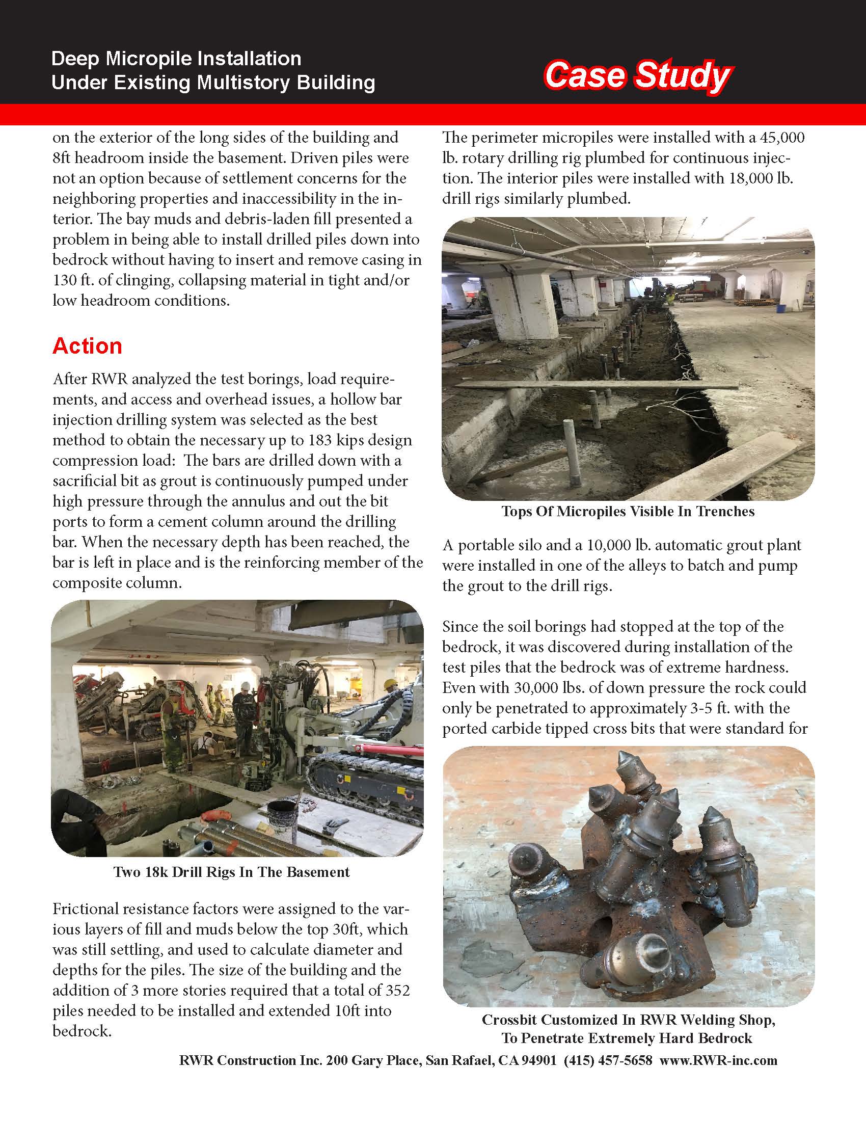
After installation of creek protection measures and grading, 180 vertical pier and horizontal tieback
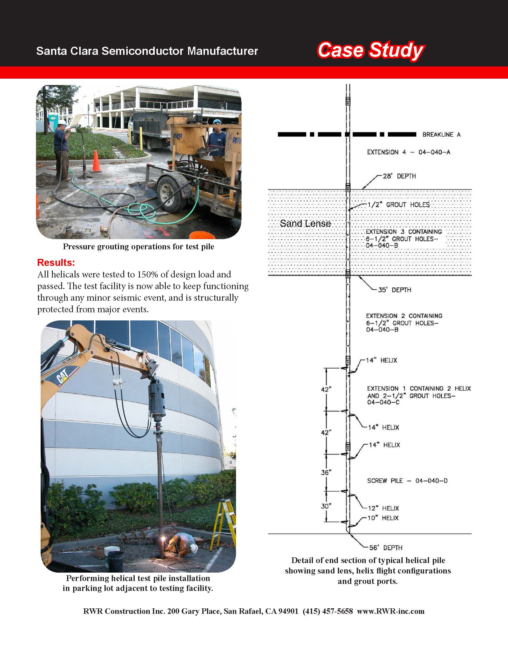
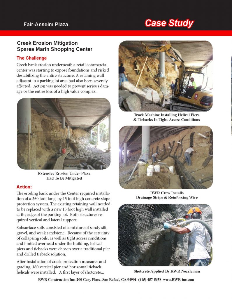
helicals were installed. A first layer of shotcrete was then applied which was laterally supported with steel plate and nut assemblies on the tensioned tiebacks.
A second layer of shotcrete was then applied to the entire project and was sculpted and colored at the parking lot to resemble native soil and stone.
Because the project was located adjacent to a creek, a total of 8 federal, state and local agencies had jurisdiction and required permits, inspections and coordination. The Federated Indians of Graton Rancheria were also involved due to the discovery of human bones during the investigation and design phase.
Because the project was on a protected waterway, all work under the Complex had to be completed by Sept. 30th, giving a construction schedule of only 2 months. RWR not only met the schedule, but also completed the job a week early.
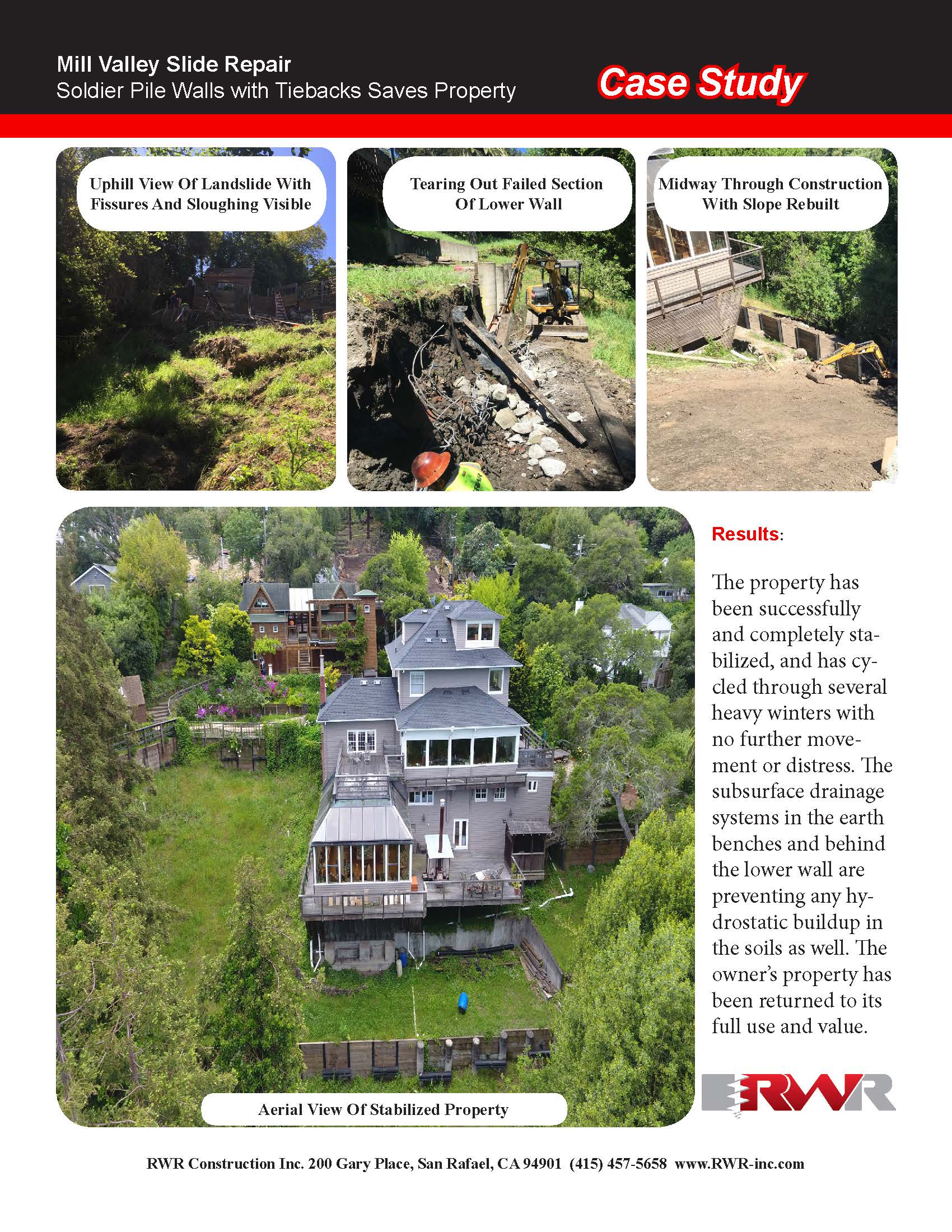
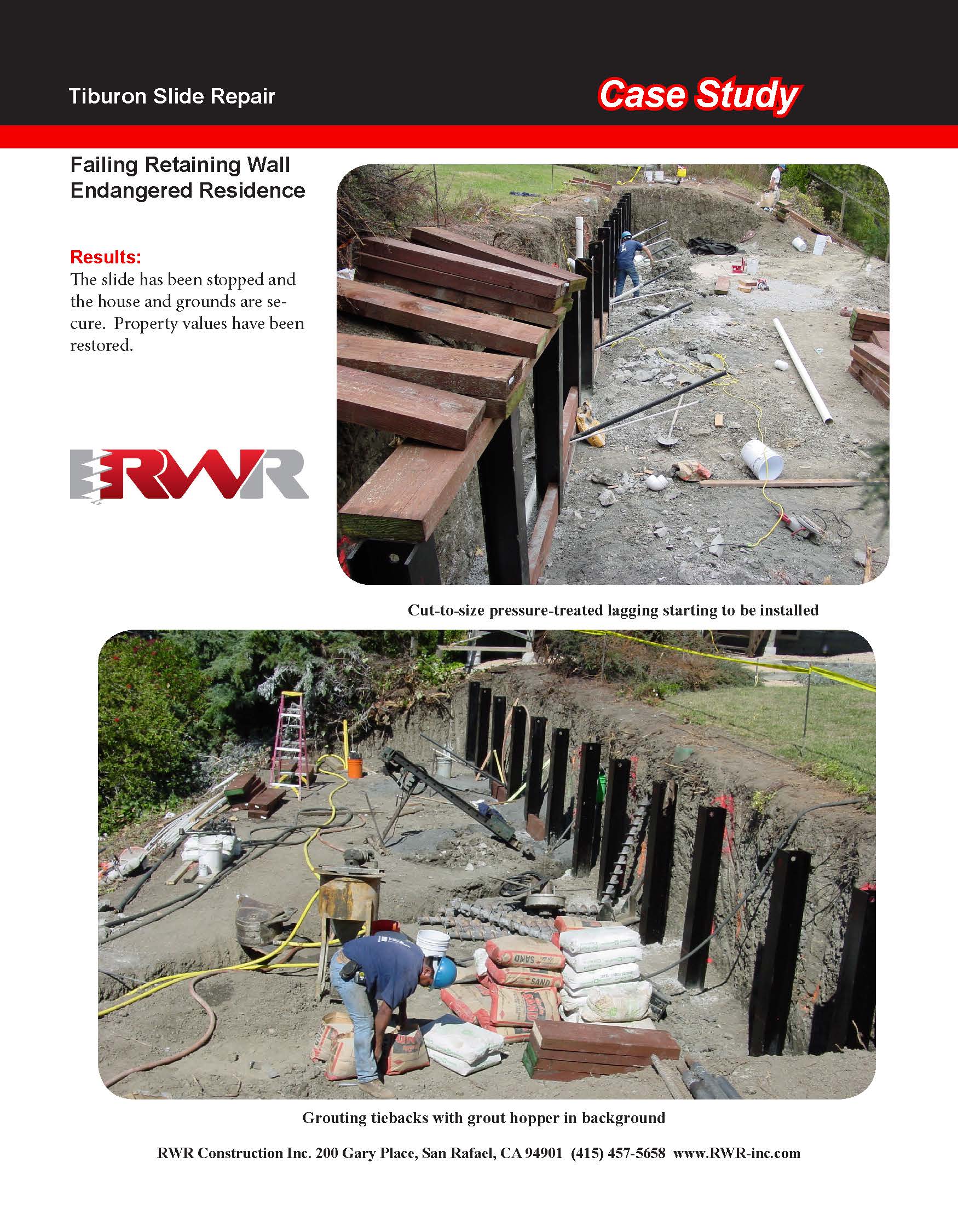
Results:
Today, the property is sound and fully occupied, and the creek no longer threatens the structure. Recent photos show the creek water crystal clear, while the building sits securely on a solid foundation over the creek banks.
Captions:
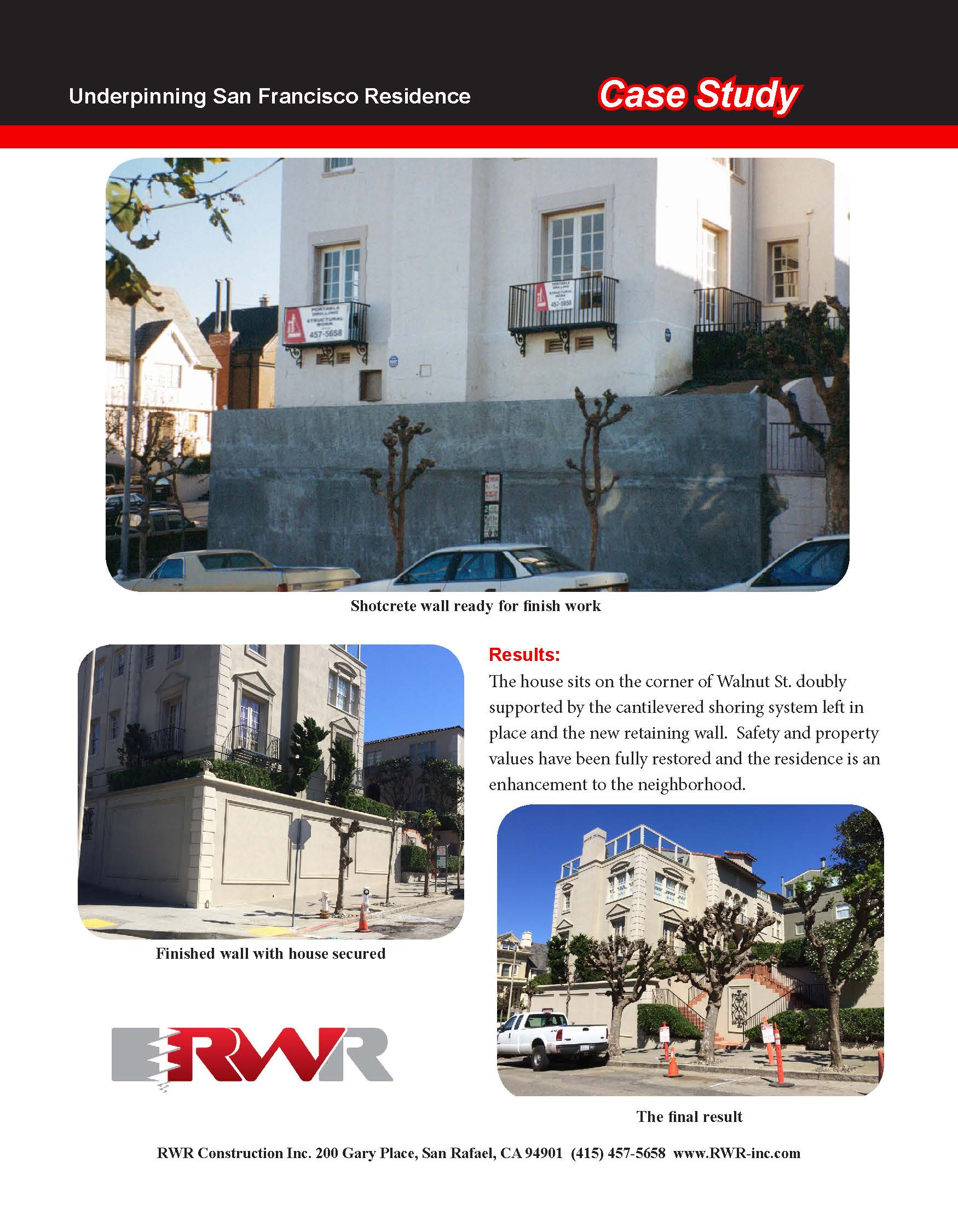
Track Machine Installing Helical Piers & Tiebacks In Tight-Access Conditions
Extensive Erosion Under Plaza Had To Be Mitigated
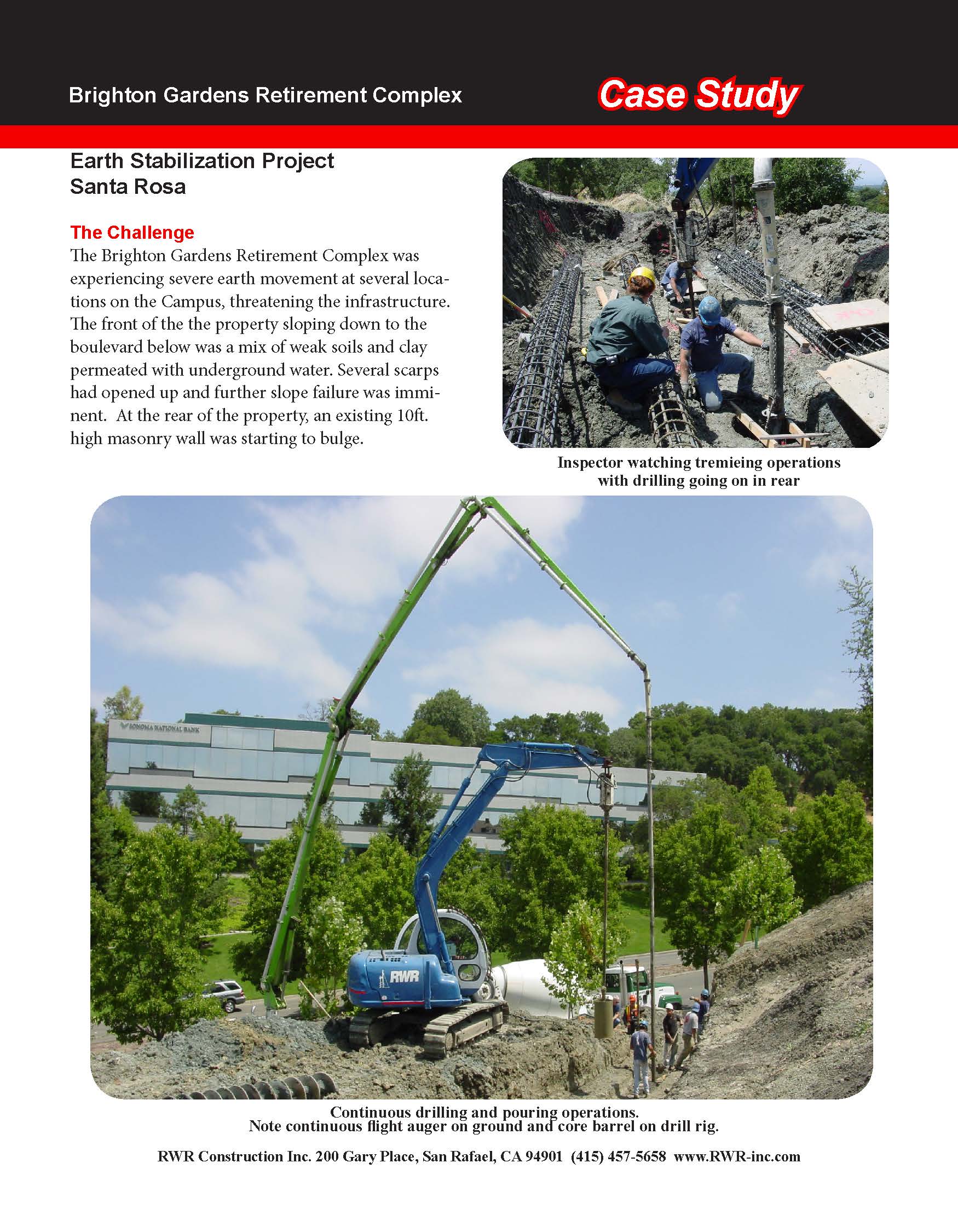
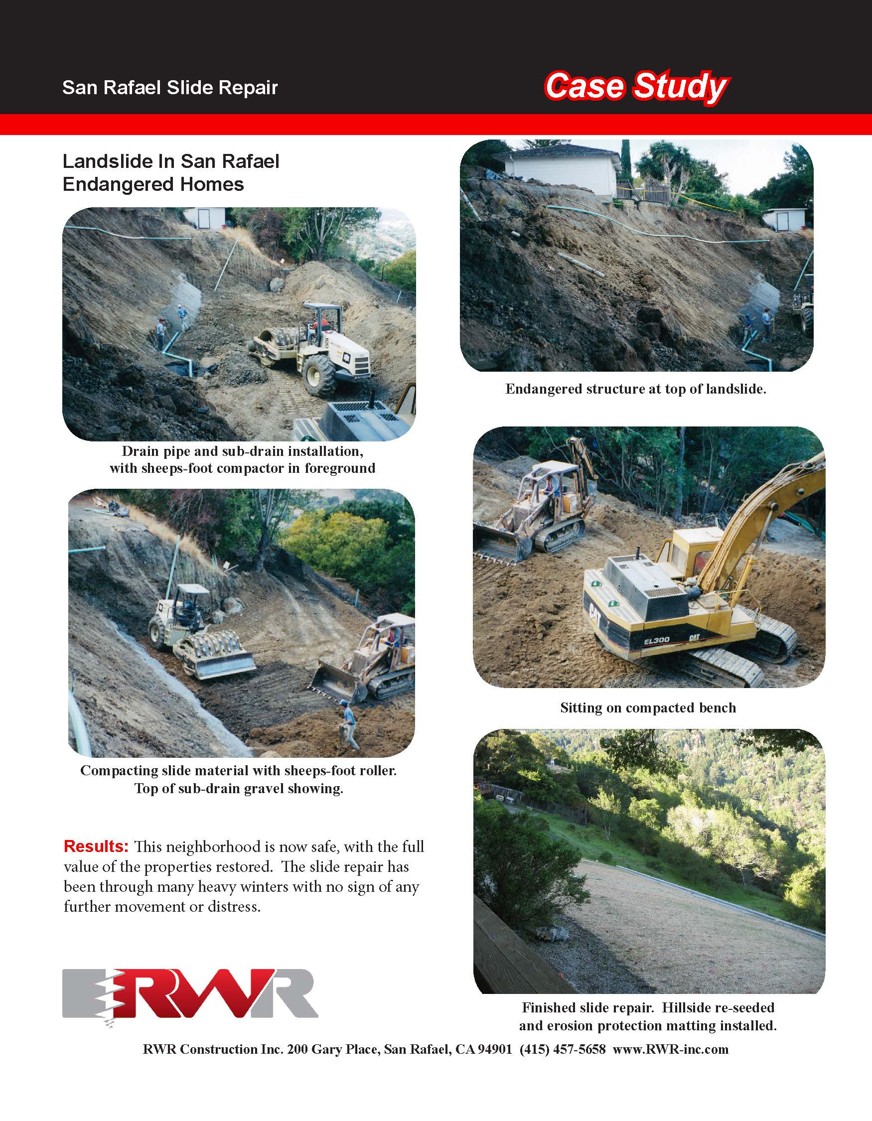
RWR Crew Installs Drainage Strips & Reinforcing Wire
Shotcrete Applied By RWR Nozzleman
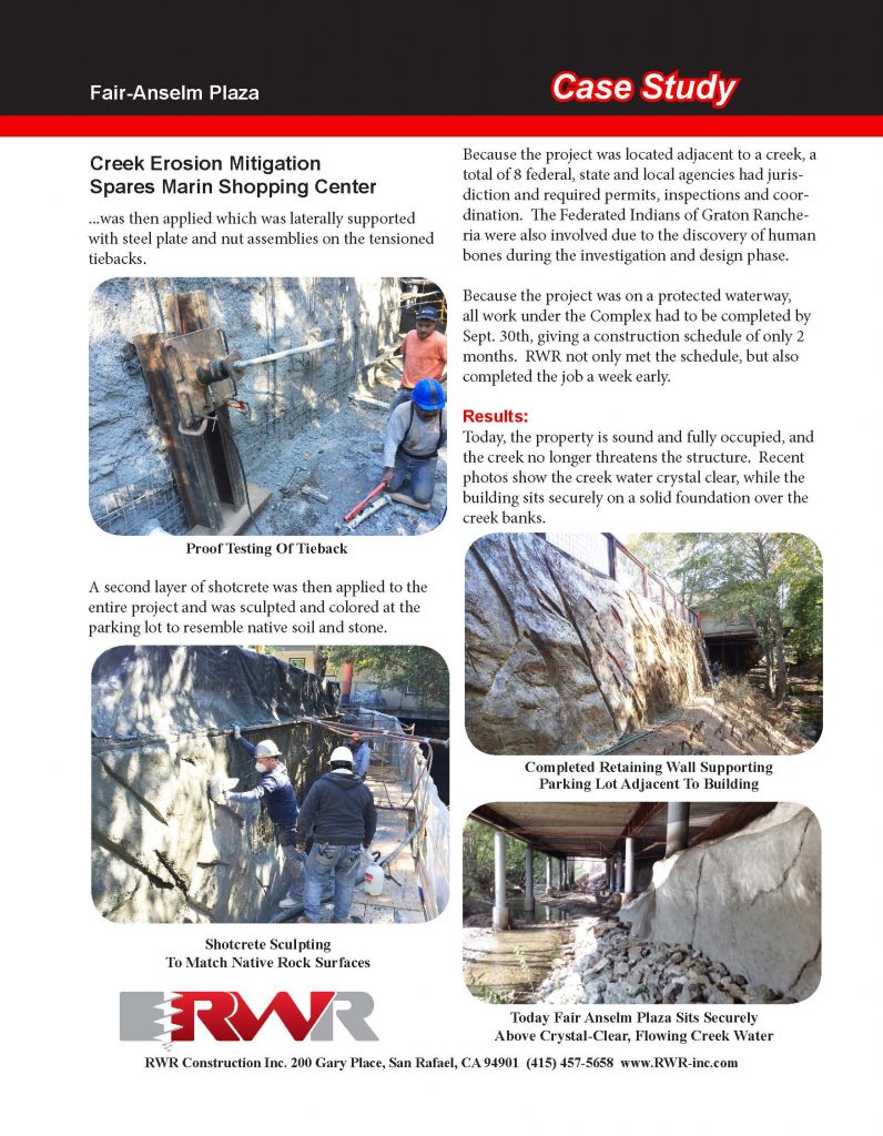
Proof Testing Of Tieback
Completed Retaining Wall Supporting Parking Lot Adjacent To Building
Shotcrete Sculpting To Match Native Rock Surfaces
Today Fair Anselm Plaza Sits Securely Above Crystal-Clear, Flowing Creek Water
RWR Construction Inc. 200 Gary Place, San Rafael, CA 94901 (415) 457-5658 www.RWR-inc.com