 Case Study: Deep Micropile Installation Under Existing Multistory Building
The Challenge
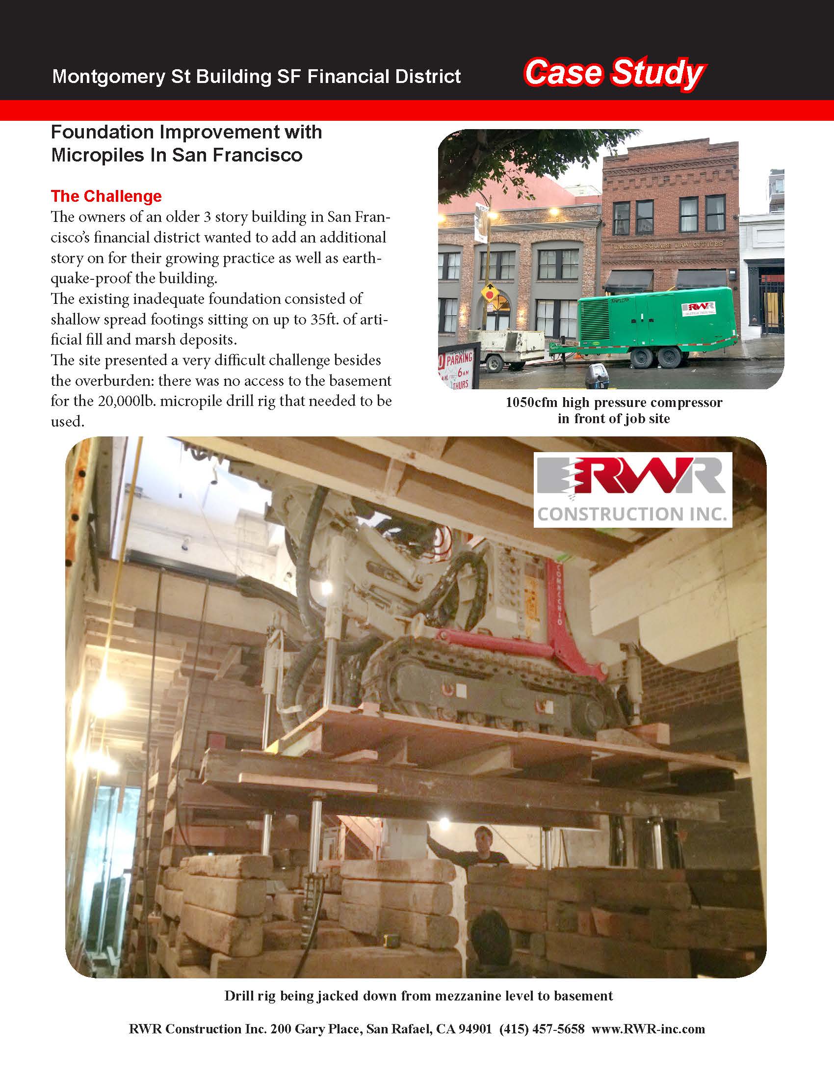
The Owners of a former warehouse located in the vibrant tech start-up area south of Market St. in San Francisco made the decision to bring the building up to current earthquake standards and to have the option to add on another 3 stories.
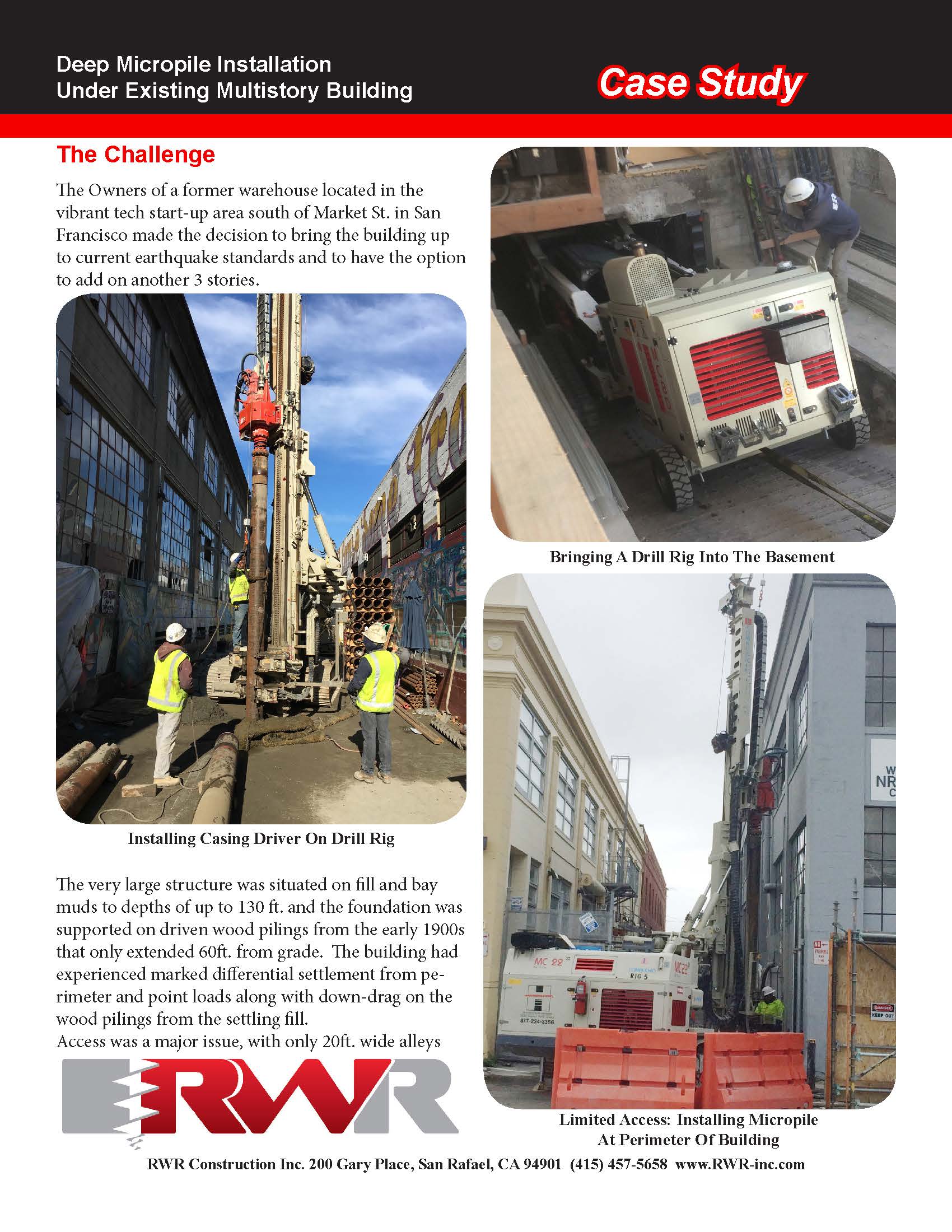
The very large structure was situated on fill and bay muds to depths of up to 130 ft. and the foundation was supported on driven wood pilings from the early 1900s that only extended 60ft. from grade. The building had experienced marked differential settlement from perimeter and point loads along with down-drag on the wood pilings from the settling fill.
Access was a major issue, with only 20ft. wide alleys on the exterior of the long sides of the building and 8ft headroom inside the basement. Driven piles were not an option because of settlement concerns for the neighboring properties and inaccessibility in the interior. The bay muds and debris-laden fill presented a problem in being able to install drilled piles down into bedrock without having to insert and remove casing in 130 ft. of clinging, collapsing material in tight and/or low headroom conditions.
Action
After RWR analyzed the test borings, load requirements, and access and overhead issues, a hollow bar injection drilling system was selected as the best method to obtain the necessary up to 183 kips design compression load: The bars are drilled down with a sacrificial bit as grout is continuously pumped under high pressure through the annulus and out the bit ports to form a cement column around the drilling bar. When the necessary depth has been reached, the bar is left in place and is the reinforcing member of the composite column.
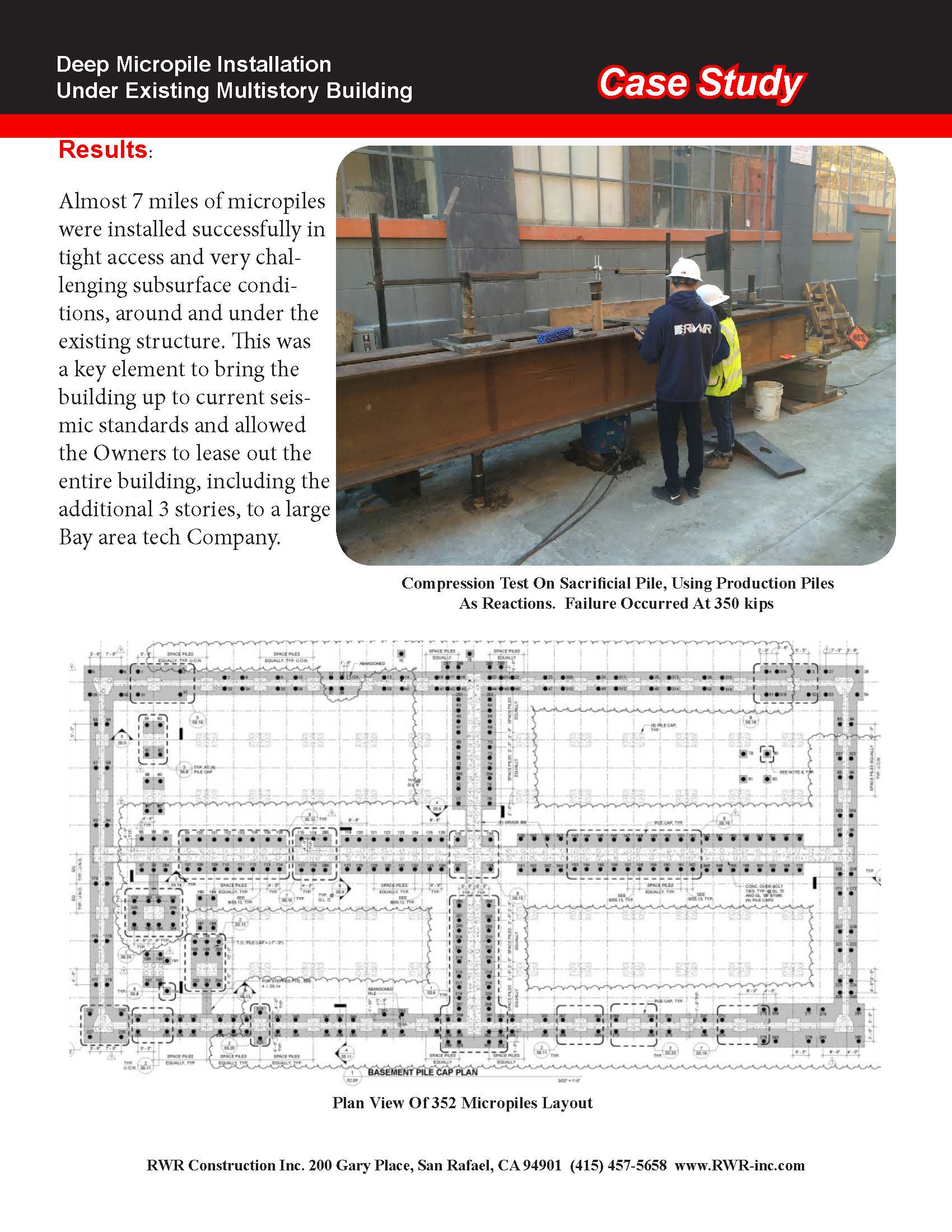
Frictional resistance factors were assigned to the various layers of fill and muds below the top 30ft, which was still settling, and used to calculate diameter and depths for the piles. The size of the building and the addition of 3 more stories required that a total of 352 piles needed to be installed and extended 10ft into bedrock.
The perimeter micropiles were installed with a 45,000 lb. rotary drilling rig plumbed for continuous injection. The interior piles were installed with 18,000 lb. drill rigs similarly plumbed.
A portable silo and a 10,000 lb. automatic grout plant were installed in one of the alleys to batch and pump the grout to the drill rigs.
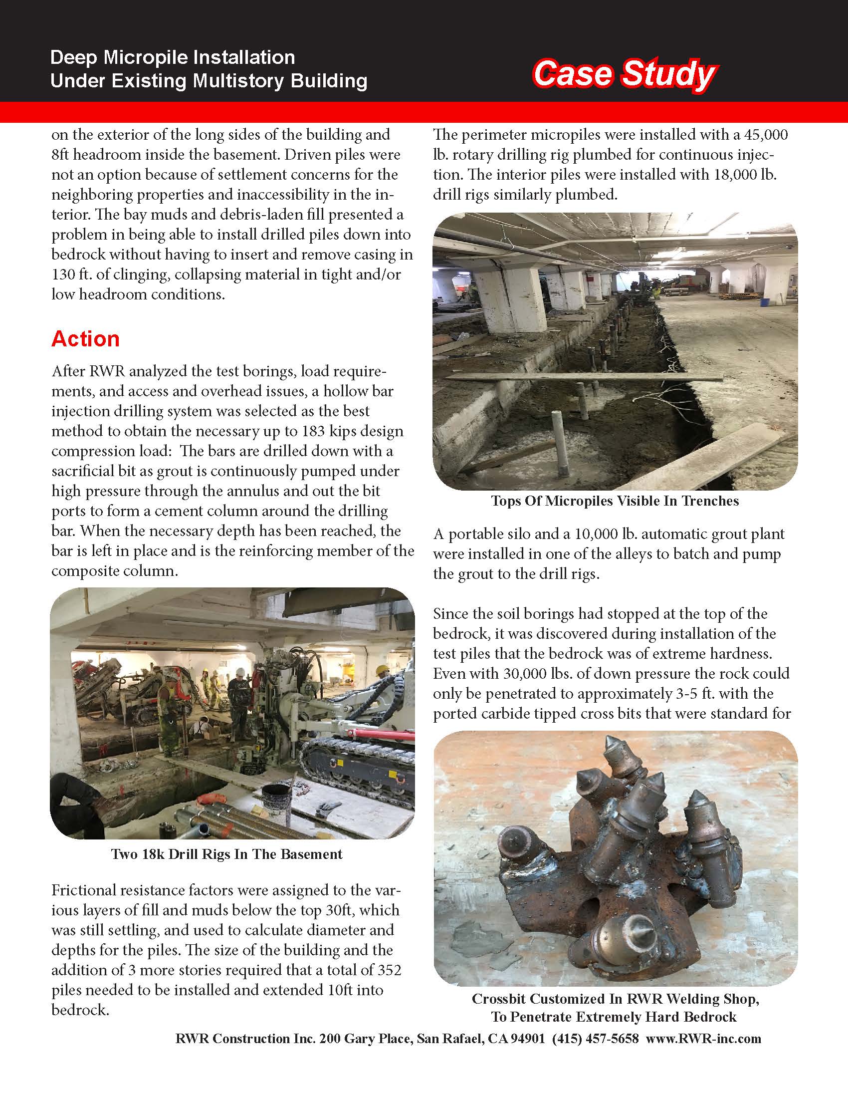
Since the soil borings had stopped at the top of the bedrock, it was discovered during installation of the test piles that the bedrock was of extreme hardness. Even with 30,000 lbs. of down pressure the rock could only be penetrated to approximately 3-5 ft. with the ported carbide tipped cross bits that were standard for rock drilling with the hollow bars. Rotary percussion was ruled out because the impact energy would mostly be lost through the extreme depths of the muds.
The bits were taken to RWR’s welding shop and after pre-heating, conical carbide tipped drill teeth were welded on to the cross bits. This adaptation allowed penetration through the bedrock to the necessary depths.
In order for the piles to have the necessary resistance to lateral earthquake forces, the top 13 ft. of all the piles were reinforced by first installing 10” diameter x ½” thick steel casing, then injection drilling through the casings. Footing trenches were already excavated in the basement so the casing was installed 13 ft. below the bottom of excavation. But the exterior was 11 ft. above bottom of footing, so a casing driver was constructed and used to insert the top of the 13 ft. long exterior casing to the proper depth. Disposable plastic piping was then inserted that reached from grade into the top of the steel casing to prevent collapsing and guide the drill bars into the casing.
The exterior micropiles were installed using 3” diameter hollow drill bars in 3 meter lengths. Due to the 8 ft. headroom, the casings in the basement were threaded and installed in 1 meter lengths and the bars in 1 meter lengths as well. All bars were connected using couplers with special metal seals that could withstand the up to 600psi grout pressures.
Due to the tight schedule, there were 2 low overhead rigs and crews operating inside, 1 rig and crew outside and a grout plant with crew. The grout plant was modified to be able to pump grout to 2 machines at once: a Y valve was installed that would direct the batched grout to either the high pressure pump on the grout plant or to a double-hopper grout plant in the basement that fed a 2nd machine. A dance of casing installation and injection grouting between the 3 rigs required constant oversight and careful scheduling.
Up to 20 tons of cement were delivered in a double hopper truck every-other morning and blown into the silo to feed the grout plant.
The grout, which consisted of neat cement and a retarder to allow for the hard rock drilling time, had a specified strength of 8000psi. There was continuous sampling of grout batches during the installation and crush results ranged from 8000 to 10,000psi after 40 days.
Three initial compression tests were performed to verify the loading requirements. 20% of all production piles were pull tested to 133% of compression design loads, which also verified tension load requirements.
Results:
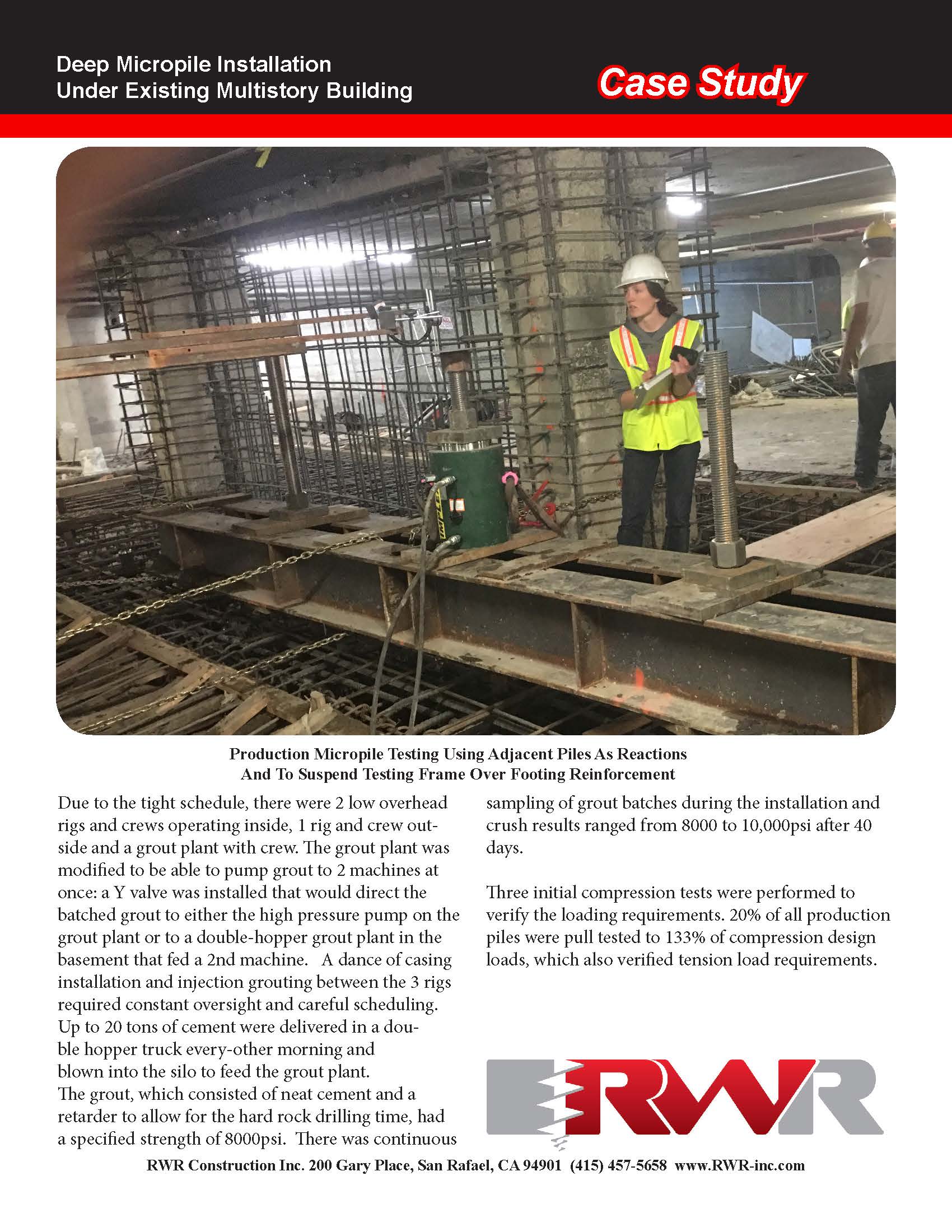
Almost 7 miles of micropiles were installed successfully in tight access and very challenging subsurface conditions, around and under the existing structure. This was a key element to bring the building up to current seismic standards and allowed the Owners to lease out the entire building, including the additional 3 stories, to a large Bay area tech Company.
Captions:
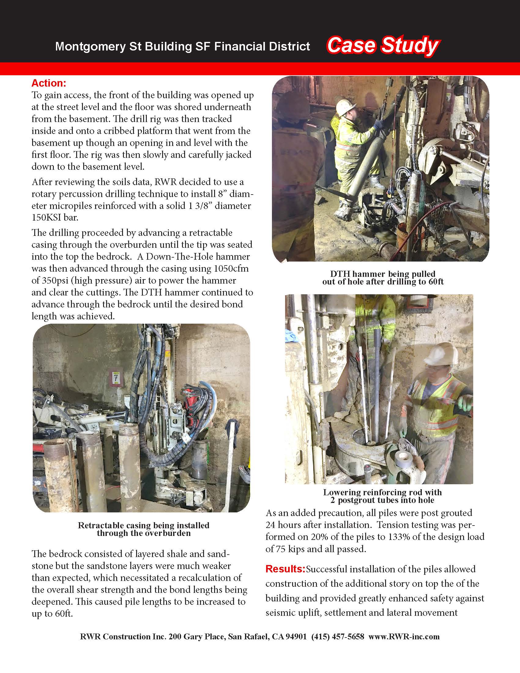
Bringing A Drill Rig Into The Basement
Installing Casing Driver On Drill Rig
Limited Access: Installing Micropile At Perimeter Of Building
Tops Of Micropiles Visible In Trenches
Two 18k Drill Rigs In The Basement
Crossbit Customized In RWR Welding Shop, To Penetrate Extremely Hard Bedrock
Exterior: Top Of Micropile With Bearing Plate & Nuts Visible Along With Plastic Sleeving At Far End
Casing And Hollow Bars For Exterior Installation
2nd Grout Pump In Basement
2 Drill Rigs Working Opposite Trenches
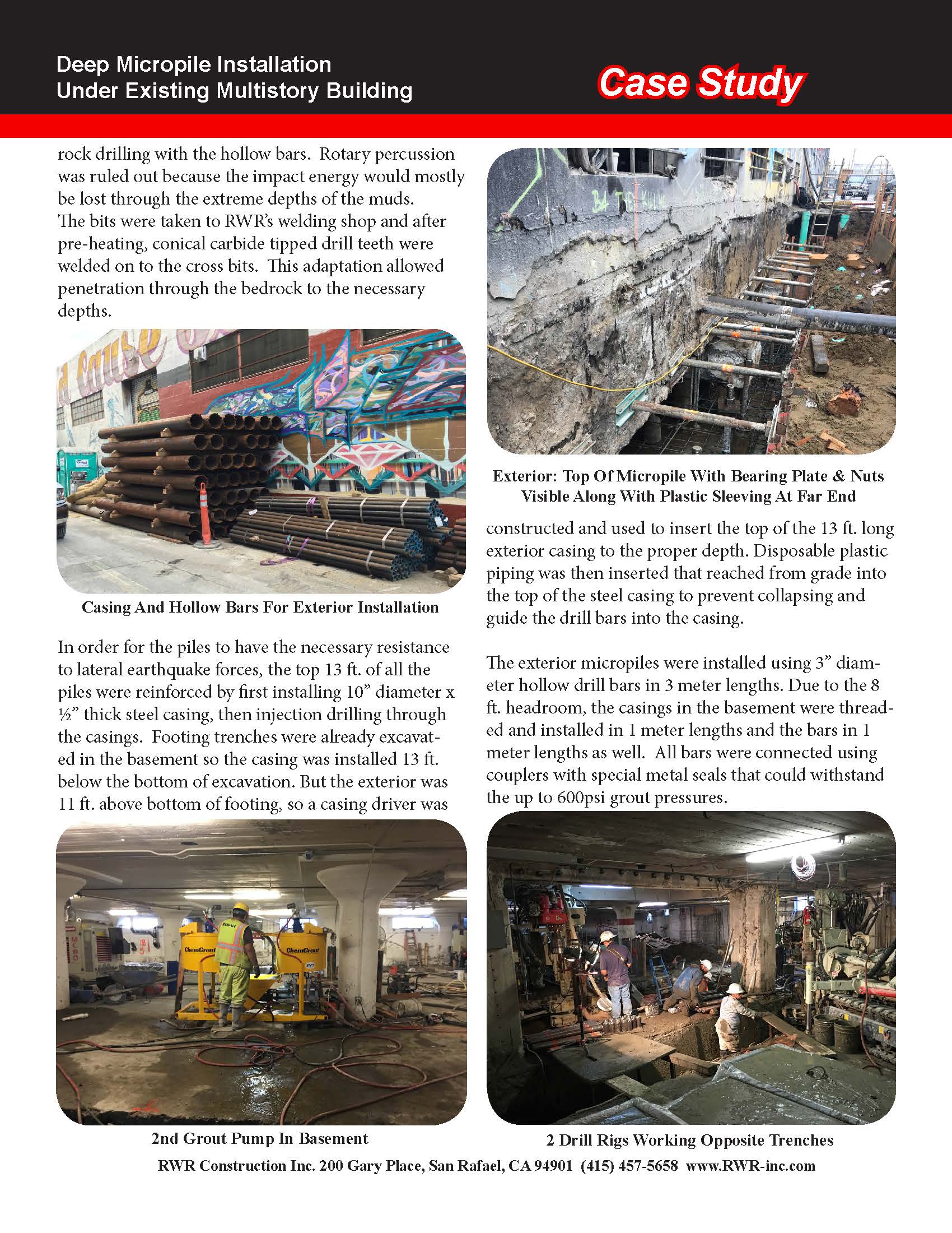
Production Micropile Testing Using Adjacent Piles As Reactions
And To Suspend Testing Frame Over Footing Reinforcement
Compression Test On Sacrificial Pile, Using Production Piles As Reactions. Failure Occurred At 350 kips
Plan View Of 352 Micropiles Layout
RWR Construction Inc. 200 Gary Place, San Rafael, CA 94901 (415) 457-5658 www.RWR-inc.com